In computer science, the way memory is interacted with by the programmer is one of the core lessons that differentiates an undergraduate education from hobbyist tinkering, and confronting the nature of memory is also a major theme in industrial conversations about a piece of code or even an entire programming language.
The computer engineering of the lowest levels of a computational circuit is the same. In capturing the behavior of a memory, we begin to build circuits which are fundamentally different from combinational logic.
(If you’ve studied functional programming, you will see combinational logic to be, in a way, its purest form, a physical system of organizing logic that literally cannot fail to be purely functional.)
Last week, we looked at the RS Latch, a simple sequential circuit that is commonly used to introduce the concept of state in digital logic. This organization of information storage is obviously a bit awkward. Something more like what we see in a computer would have a single input for the bit of data we mean to hold, and another input to dictate whether we are writing or not. (Reading and writing a memory as commands rather than wires is actually outside the scope of this article, more on that later…)
We can do this by attaching some combinational logic to the input of the RS latch to create the D-latch, or transparent latch:
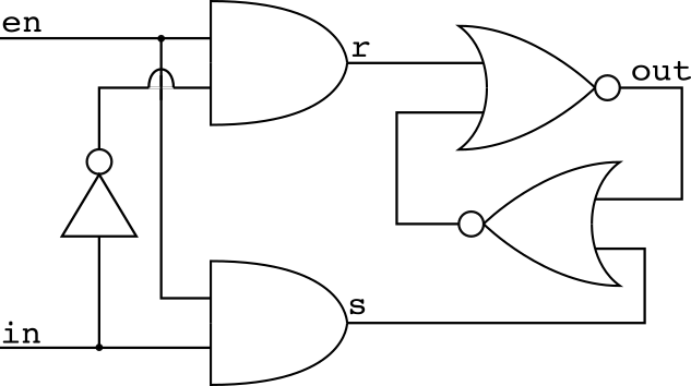
In cases where en is 0, r and s are 0 so the latch holds its state. If en is 1, a 1 appears on r or s depending on whether in is 1 or 0, so the whole assembly acts like a wire if en is high, but holds on to the last value in had if en goes low.
Usually, for system performance reasons, two of these are put back to back to create a circuit which responds to edges on en rather than levels, creating what we call the D Flip Flop, often presented as the fundamental building block of computer memory. Here’s what that looks like in verilog:
module dlatch(output o, input d, input en);
  wire d_n, s, r, o_n;
  and x1(s, d, en);
  and x2(r, d_n, en);
  not x3(d_n, d);
  nor x4(o_n, s, o);
  nor x5(o, r, o_n);
endmodule

module dff(output q, input d, input clk);
  wire clk_n;
  not x1(clk_n, clk);
  dlatch x2(q_m, d, clk_n);
  dlatch x3(q, d, clk);
endmodule
The module definition for dlatch saves about four lines of text, but perhaps more importantly makes it a lot easier to parse what’s going on here. The two latches are enabled on opposite values of the input clock, so when the clock is low, values are being sent from the input to the output of the first dlatch x2, where they are ignored by the second dlatch x3. On the event of the clock changing to a high value, x2 stops looking at q and begins holding a steady value. At the same time, x3 begins reporting the value at the output of x2. Thus a D Flip Flop is edge triggered, a property which is very helpful for timing reasons. (It must be, if virtually all CPUs are willing to double the physical size of their registers to do it!)
There is of course an easier way: behavioral modeling. It is possible to represent the behavior of the above circuit much more compactly in verilog than with its full set of logic gates (which aren’t the actual implementation in use today anyway), while preserving the behavior of that circuit. The entire code for that is just this:
module dff(output q, input d, input clk);
  reg q_reg; //stored information
  assign q = q_reg; //storage always outputs
  //Below is event-driven "code"
  always@(posedge clk)
  begin
    q_reg=d;
  end
endmodule
(Technically I could make this more compact, but I wanted comments and legibility.) The above code does everything the full gate model does, but with less code and more room to expand and start representing true computer memory.
As usual, check out the github repository for this source code, and a test bench to show it working. As an exercise to make sure the simulation makes sense to you, you can try editing the code after “initial begin” in the bench module to change what input signals are applied and see how the circuits behave.