Let’s look at an example of a Verilog file that contains some modules. In the previous demonstration file, I lumped everything together into a single module called “test”. This is fine for simple modules (by which I mean modules which are simple to describe, not necessarily simple to build), but at scale, organization is handy. This module will also illustrate a simple example of two different approaches to the same modeling problem.
module inv1(output o, input i);
 assign o=~i;
endmodule

module inv2(output o, input i);
 not x(o,i);
endmodule

module bench;
 reg in;
 wire out1,out2;

 inv1 x1(out1,in);
 inv2 x2(out2,in);

 initial begin
  $dumpvars(0,bench);
  #5;
  in=0;
  #5;
  in=1;
  #5;
  $finish;
 end
endmodule
Here’s the same circuit as a block diagram:
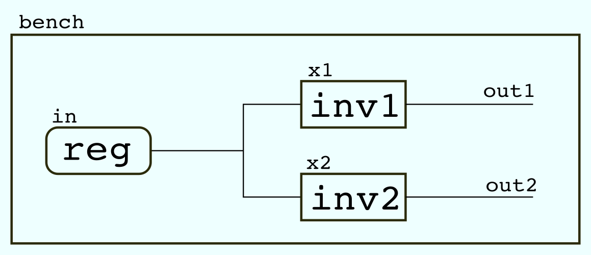
The register “in” is simultaneously a node and an object, which is a little confusing for hardware types like me but is at least consistent: a reg will always be both a “voltage source” (or more precisely, a bit of state contained in the simulation) and a net in the simulation. This behavior is also present in the input and output keywords, which will imply the presence of nets inside a module. The “initial” block of code is the only thing in this file that represents sequential behavior. Everything else is a model of some physical piece of hardware.
The two inverter modules contain code which looks suspiciously like software, so let’s drill down into both of them. Despite their appearance, neither of these definitions represents a “command” in any real sense. They declare relationships which will be updated by the simulator.
The first, inv1, uses the assign keyword to establish a logical relationship, o=~i. Any change to the value of i will cause o to be updated to its compliment. You could in theory include multiple assignments, but to make them work “properly” you would need to take a look at “blocking” vs “non-blocking” assignment, a thorny subject that I will leave aside for now. (Suffice to say, when constructing a complex logic statement, it’s important to remember that Verilog’s C-like aesthetic is only skin deep in a lot of places.) This assignment operator is however considered “behavioral” because it specifies a logical relationship rather than any internal physical components. How you get inversion out of this block is not specified by it.
The second, inv2, instantiates an inverter from Verilog’s list of stock hardware blocks. “not x(o, i)” implies the existence of an inverter called “x” and specifies that a hardware implementation of this block should be done with a single inverter. (Not, for example, nine, which would also work, and might even exist in the case of an output driver.) This is “structural” Verilog because it describes specific physical hardware. All Verilog specifies hardware, but structural Verilog specifies how the hardware comes to behave as it does in simulation.
Although these are trivial examples which use the same number of lines to do the same thing, they represent paths which can become extremely divergent when modeling more complex hardware.