When students in beginning digital circuit classes begin learning Hardware Descriptive Languages (HDLs), it’s often through a big, heavy GUI tool like Quartus. If you stick to small examples, this works fine, but in bigger tasks things can start to slow down a lot. It’s because of these slowdowns that I use Icarus Verilog instead.
Like a lot of tools in the EDA world, Icarus Verilog is a lot easier to install on Linux than Windows, but there is some good news for those of you on Windows 10: Windows Subsystem for Linux exists.
(Very confusingly named as this is a mini Linux running on your Windows machine.)
All my instructions for this are going to assume you’re using a version of Linux similar to the WSL, but that includes everyone on Ubuntu and Ubuntu-like operating systems so it’s pretty good coverage. Installing on one of these systems is really easy, you just get a command window open and type:
sudo apt install iverilog gtkwave
(Funny story for Windows users, Linux has spent its whole life on the internet, and as such had an app store since, um, 1994. It was text-based, but worked just like an app store today, minus the ability to charge money. Apt still works the same way.)
The above command installs two pieces of software, Icarus Verilog and GTKWave. (Icarus Verilog doesn’t have any way to show you waveforms! You need a separate piece of software to do that, hence the second tool.) Icarus Verilog is a purely text-based system. That probably made it sound hard, so let’s do a quick Hello World in verilog, which for digital logic is the following circuit:

The position of A at the input of the inverter above implies that it must be a voltage source, so we’ll need to use the HDL to invoke something that puts values into A. In verilog we call this a reg. To make sure it’s working, we should have A go to both binary values 0 and 1. So here’s a verilog file:
module test;
   reg A;
   wire Y;
   not x(Y,A);
   initial begin
      $dumpvars(0,test);
      #10;
      A=0;
      #10;
      A=1;
      #10;
   end
endmodule
The outermost block of text is the module declaration, which represents all things to be simulated. Inside there are four items, a reg object (the voltage source I mentioned earlier), a wire object to connect the output, the inverter itself, implemented by the “not” keyword, and the test program. (The test program is everything between “initial begin” and “end”.) Of these, only the test program actually runs sequentially. The rest could appear in any order.
Next, you need to run the simulator. Icarus Verilog does this in two steps: first it compiles to an intermediary language called vvp assembly, then it runs that assembly with another program named vvp, which was installed automatically as part of Icarus Verilog. Assuming we named the file above test.v, you’d type:
iverilog test.v
vvp a.out
(The default file name a.out should be familiar to c programmers!)
When you run vvp, you’ll be informed that a file named “dump.vcd” has been opened for output. This is the file you want to ask GTKWave to look at:
gtkwave dump.vcd
And at this point, you’ll get an actual GUI app, and you can use it to look at the two signals in this system, A and Y.
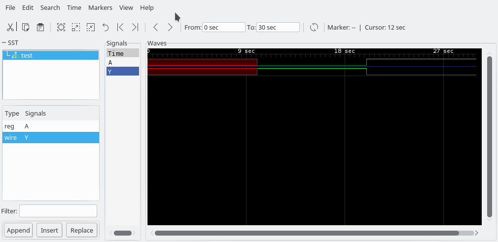
(You won’t immediately see the waves, you have to click test, then drag A and Y into the pane that says “Signals”.)
Now we have a time-domain waveform of an inverter doing its thing. This might seem like a lot of work to get such a rudimentary simulation running, but verilog can be used to simulate just about any digital system you can think of, and Icarus Verilog in particular does so very quickly, even with big, complex digital circuits.
To give you some idea of how fast, I have a project over on GitHub that simulates an entire miniature CPU with its own instruction set. It runs basically instantaneously even when executing 100 or so instructions!
There’s a great course online that uses HDL: nand2tetris.org
It doesn’t use verilog, for good reasons, but if I were to do something similar, I’d definitely use verilog, if for no other reason than how ubiquitous it has become in actual VLSI jobs. Maybe I’ll do that in part right here!